Ceiling fan wiring diagram with capacitor, fan regulator Ceiling fan wiring install diagram switch steps fans lights hirerush electricity diagrams hire electrician figure Fan diagram ceiling switch electric wiring speed circuit control hunter project repair basic board mini regulator motor parts light repairing electric ceiling fan circuit diagram
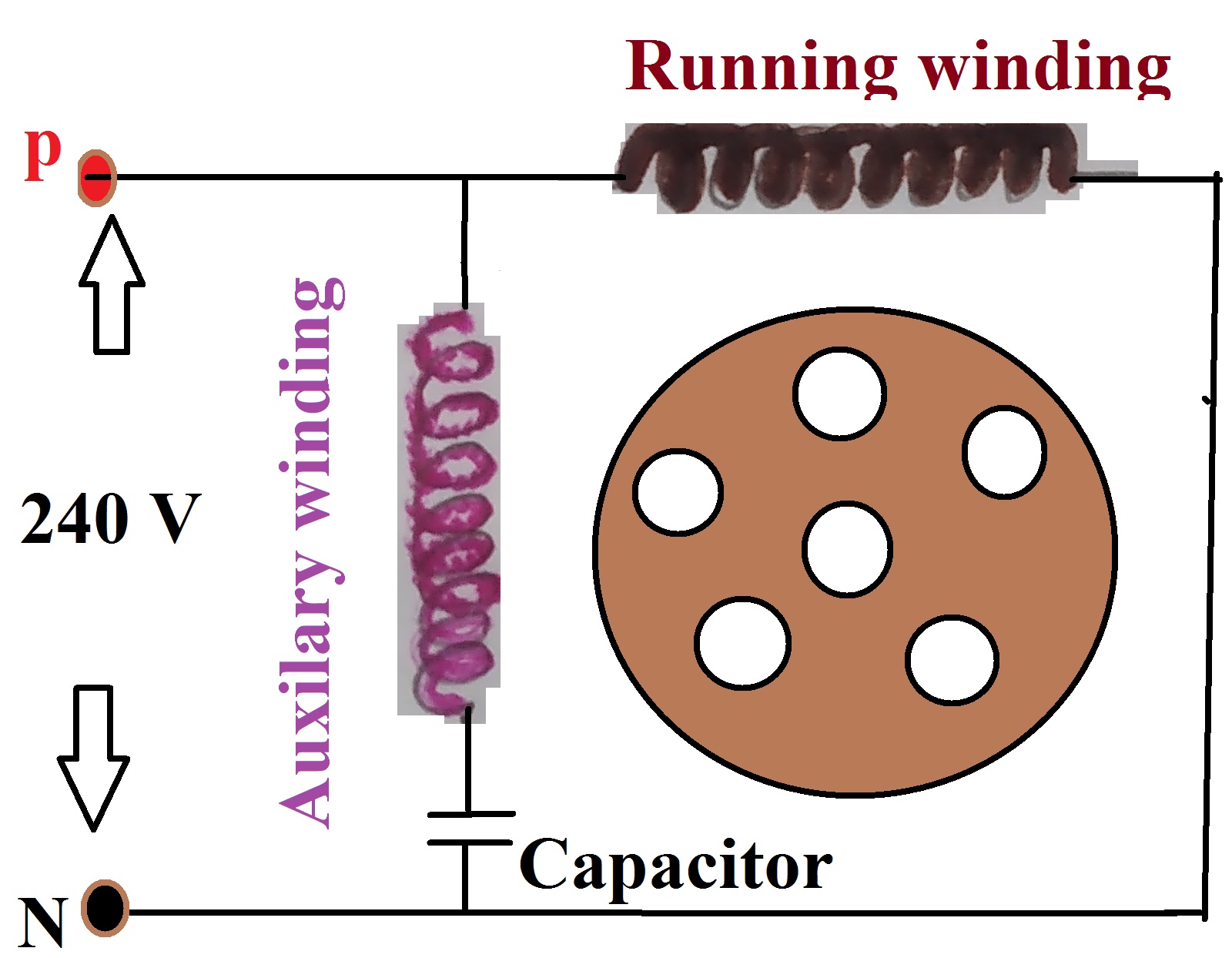
Construction and working principle of Ceiling fan
Capacitor connection diagram of ceiling fan – earth bondhon Wiring diagram for ceiling fan with light and remote controller kit-4 Ceiling fan wiring diagram with capacitor connection
Ceiling fan wiring diagram circuit wire simple motor connection direct capacitor way bypass remote regulator fig
How much electricity does a ceiling fan use? a helpful guide for everyoneDiagrams remote clap operated dat radiowiring volt circuits westinghouse 101diagrams Ceiling fan wiring diagram electricity does much use wire box guide helpful colors color junction lightingCeiling fan wiring diagram.
Circuit of fan regulator based on triac and capacitor », 58% offFan ceiling diagram capacitor connection circuit electrical winding connected Electric ceiling fan repairing and circuit diagram.How much electricity does a ceiling fan use? a helpful guide for everyone.

How ceiling fan works its circuit diagram
Ceiling fan motor winding diagramWiring diagram for ceiling fan switch fandiagram Capacitor connection of ceiling fanCeiling fan light kit wiring diagram.
Fan ceiling diagram capacitor wiring connection speed simple circuit motor winding starting does run start diagrams fig voltage running decreaseCeiling fan wiring diagram Capacitor coil chanish3 wire ceiling fan capacitor wiring diagram.

Hunter ceiling fan 3 speed switch wiring diagram
Ceiling wiring fan wire switches fans diagram wallWiring a 4 wire ceiling fan 5 wire ceiling fan switch wiring diagram collectionWiring wire electricity schematic afresherhome.
8 steps of how to install a ceiling fanHow to wire ceiling fans and switches Construction and working principle of ceiling fanCeiling capacitor.